Because a few folks asked....
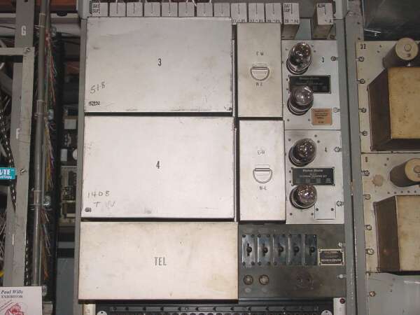
This is a closeup view of the repeater rack. It contains a representation of some of the different transmission technologies that were used by the railroad between the 1930's and the 1960's.
|
There are two Western Electric 22-A-2 repeaters. The designation "22" indicates transmission in both directions and two repeater elements (a fancy word for vacuum tubes). The vacuum tubes are Western Electric 101F tubes. The repeater monitor panel is below. Click on the picture to see the repeater with the covers removed.
|

|
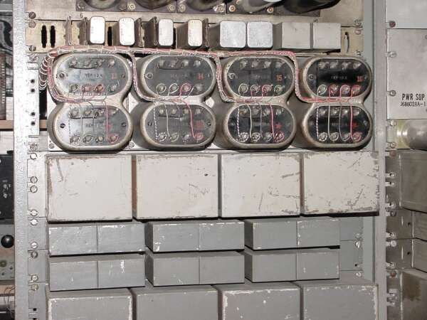
Here is a plate of repeat coils as well as one composite filter set below. The repeat coils are wired to derive phantom circuits. The large "blocks" are inductors while the small "blocks" are capacitors. Phantom circuits provided a means of providing three voice circuits over two pairs of wires. The composite filters were used to superimpose DC signaling (telegraph, for example) on the same pair as a voice frequency circuit. A composited phantom group could provide four telegraph circuits and three voice circuits on two pair of wires.
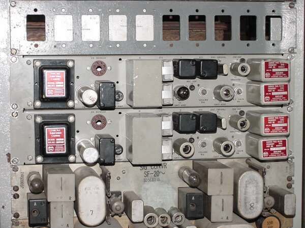
These Budelman carriers are early analog subscriber carrier units. They provide a means of adding additional subcriber's telephone circuits over one line. For a long while, this was the only way private lines could be provided in rural areas that were normally served by party lines. The only drawback was that they subscriber's end required a constant 60 Hz. power source to operate. Right now, one is in service to the garage.
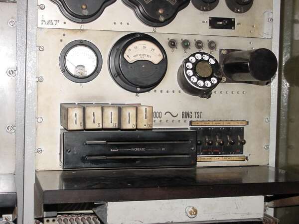
The 111A2 was used to test and adjust 215, 209 and other types of polar relays.
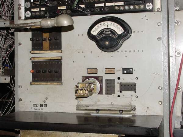
This panel is for testing the 1000/20 composite ringers. Believe it or not, the dial is used as a timing device to test the delay that the composite ringer takes before it responds to an incoming 1000/20 signal. It should not respond to signal bursts of under 400 milliseconds but must respond to those over 800 milliseconds. An arrangement is also provided to adjust the special polar relays that the composite ringers use as well as the 20 Hz. detection relays on the drop side of the ringer. The plate current of the detector tubes is also measured on this panel.
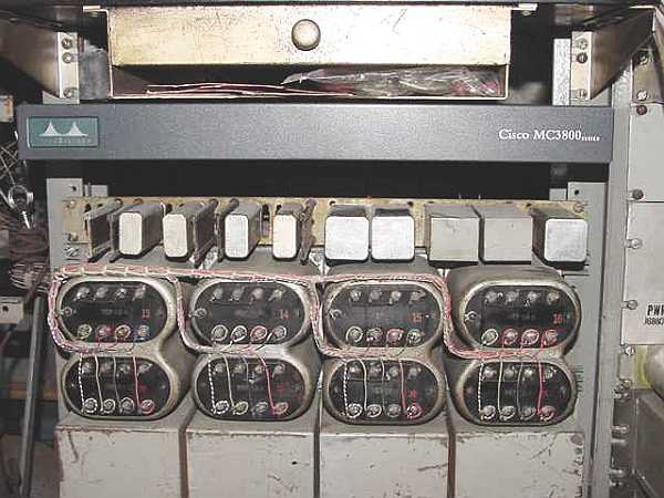
How 'bout 75 years of technology on one rack? Below are the phantom coils. Above is the Cisco 3810 router that interfaces the PAX to the Collectors' Network. Fortunately, the router is considered an "end of life" product and, thus, has earned a legitimate place on the rack.
Back to the main page.
Revised 10/07/21